Imaginative Realities
Cyber Security and Stray Thoughts
8 November 2024
Installing Game of Active Directory on Proxmox: Part 1 - Networking
by Chris
Scope of This Series
In this series of blog posts I detail how to install Orange Cyberdefense’s Game of Active Directory (GOAD) on Proxmox VE. These posts closely follow Mayfly277’s canonical guide, except that I configure GOAD on a locally hosted Proxmox VE server with an already established default network bridge connected to a true LAN. So if you’re having trouble, whether with my guide or Mayfly277’s, you may want to visit Mayfly277’s blog to compare and correlate our steps to identify where your setup may differ from each of ours.
Rationale
Why write another guide when Mayfly277’s guide is solid? First, while Mayfly277’s guide isn’t exactly out of date, technology is always moving and another set of current instructions couldn’t hurt. Second, Mayfly277’s guide focuses on a VPS setup using Proxmox, while this one details a home-lab, bare-metal install of Proxmox. Third, using Proxmox with GOAD, while perhaps easier than installing all of the Windows machines and setting up AD manually, is still sufficiently complicated that I would have benefited from having more than one set of detailed instructions. So I intentionally mirror Mayfly277’s guide in order to give readers a comprehensive set of slightly differently written resources to draw from.
That said, this blog won’t cover steps dealing with Proxmox VE installation and configuration. I’ve covered how to install proxmox elsewhere, and in any case, it’d make this series unremitting to include the Proxmox config, the downloading and loading of isos, as well as all of the GOAD-specific setup. Instead I’ll cover how to use an existing Proxmox VE installation to install pfSense and the other requirements for GOAD. Additionally, I won’t be covering theories behind Linux, Active Directory or networking in this guide. These posts are written solely for instruction on deployment steps.
Please note that I have not added screenshots for every step.
Part I: Networking
Creating the GOAD Network in Proxmox
By default, Proxmox VE will set up a network bridge in instances of on-premise/existing network infrastructure. It’ll look something like this:

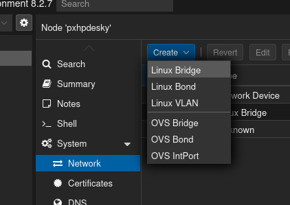
Now create the WAN and LAN networks by clicking on one of your nodes, selecting the “Network” option on the right, and then clicking on “Create” and selecting “Linux Bridge.” In the screenshots below, I’ve chosen a different subnet of 192.168.2.0/24 for the GOAD LAN and different VLAN tag numbers.
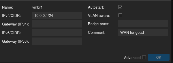
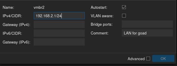
Now create another Linux Bridge for the VLANs, but this time in the dialog box that comes up make sure that the “VLAN aware” box is selected.
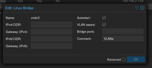
Next, create the two VLANs.
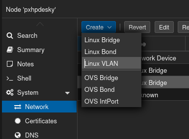
Again, I’m going to select different VLAN ranges due to Mayfly277’s selections conflicting with mine:
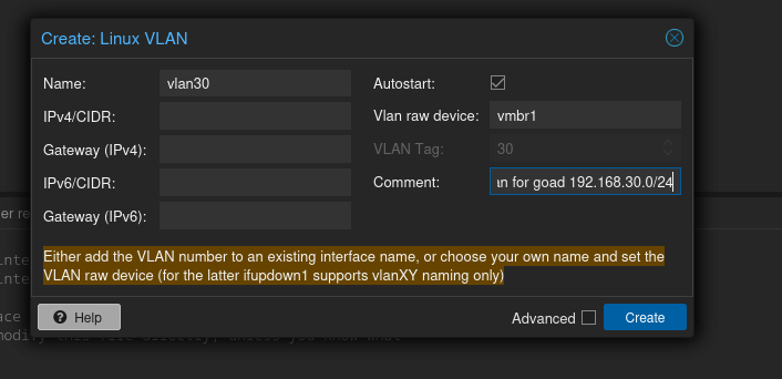
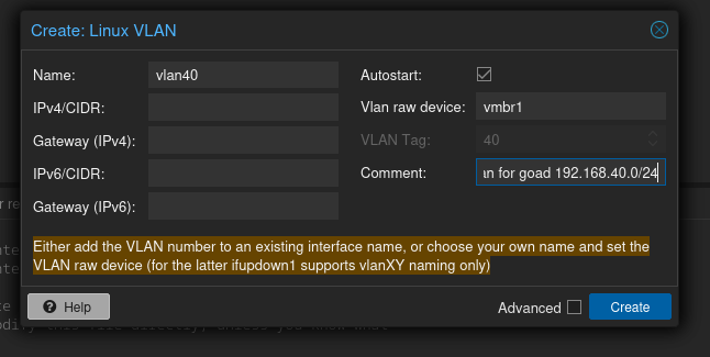
When you are finished click the “Apply Configuration” button at the top

By the end, your network setup might look like this:

Create the pfSense VM
I won’t cover obtaining and uploading images, but for a refresher, try Ben Heater’s blog. To obtain the pfSense iso, Heater also identified a site where you can download the pfSense iso without handing over your personal information.
Select one of the storage units under your node, and click the “ISO images” selection if you have it:
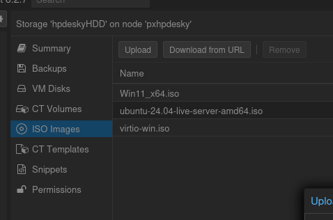
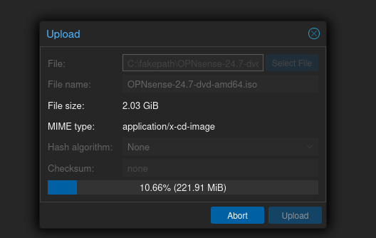
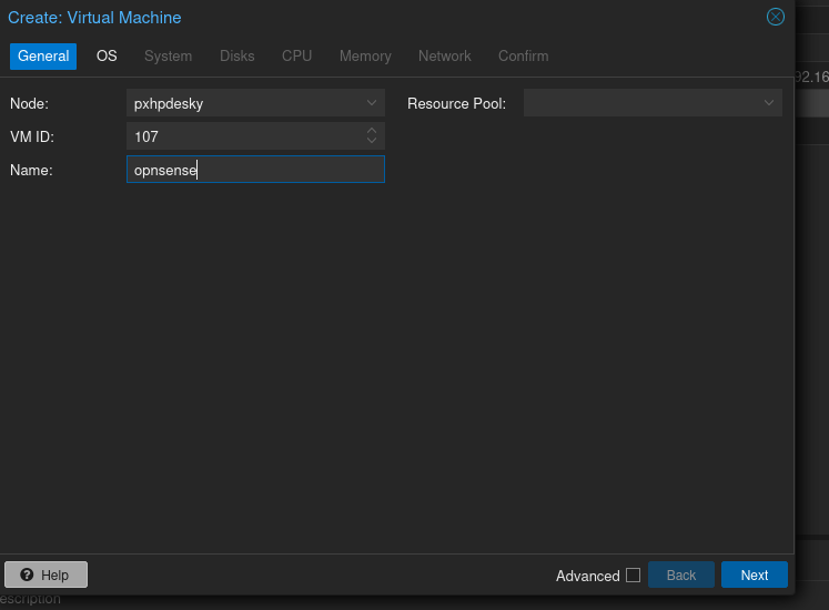
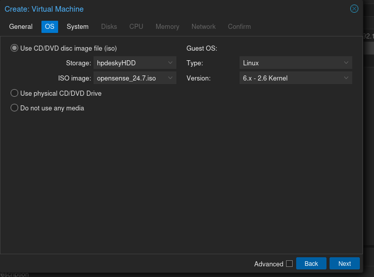
Create the VM with the roughly the same specs as Mayfly277: 2 cores, 4 GB RAM, 32 GB storage, and select the ISO you just uploaded. Otherwise accept defaults on all except on the Network tab.

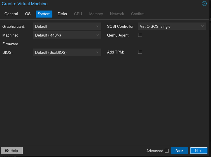
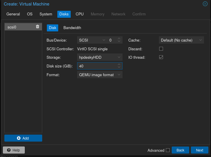
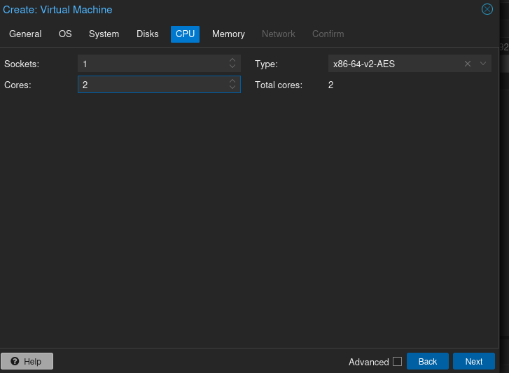
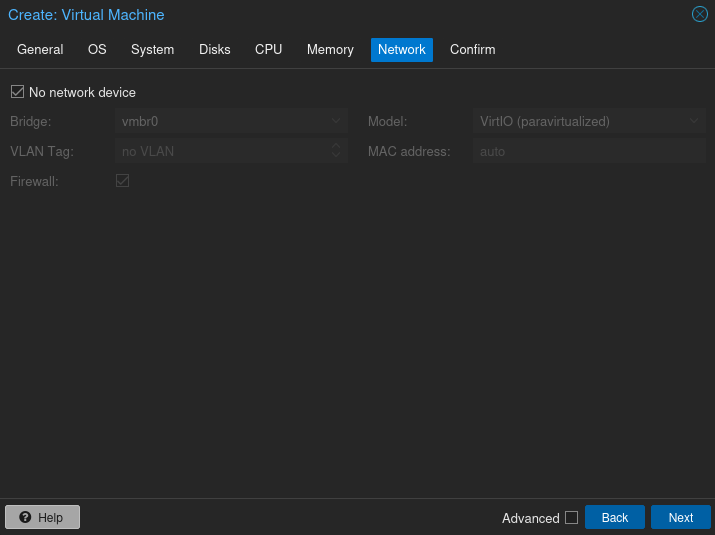
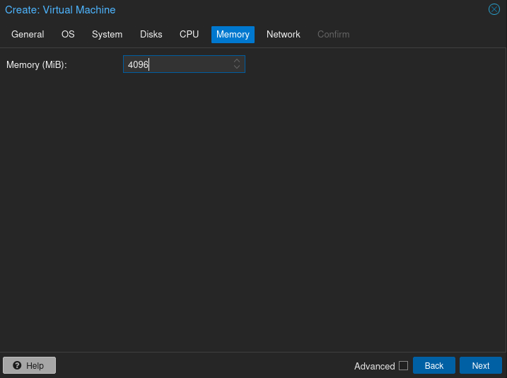 At the Network tab, select “No network” to delete the automatically populated option (it was my local LAN in my case).
Review the specs and ensure the box to start the vm after you are done is unchecked.
Next, add the WAN (called vmbr1) and LAN (called vmbr2) Linux bridges you just created, as well as the VLAN (called vmbr3).
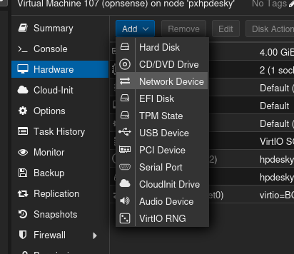

Initializing the pfSense VM
Now start up the new pfSense VM. This next part will consist of installing with a ZFS configuration, followed by an initial configuration of the WAN and LAN networks on the command line.
ZFS Selection and pfSense Base Install
You’ll see a boot up screen, and it’ll automatically begin some basic configuration before it gets to selections for install.
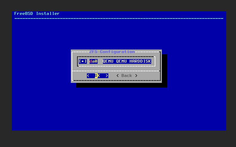
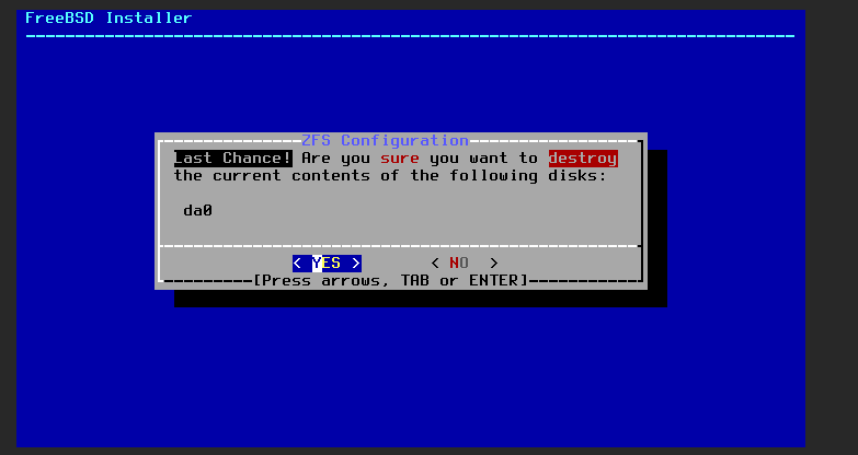
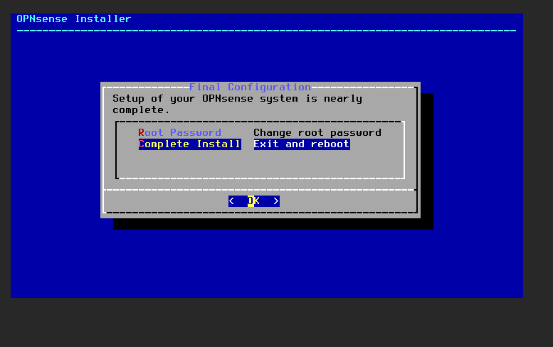
Then login and you’ll install. If it asks you for login credentials, use installer:pfSense. Note: the screenshots below are from an OPNSense but they are really the same.
Hit space bar to select the only option and tab to select “OK”.
 Select yes.
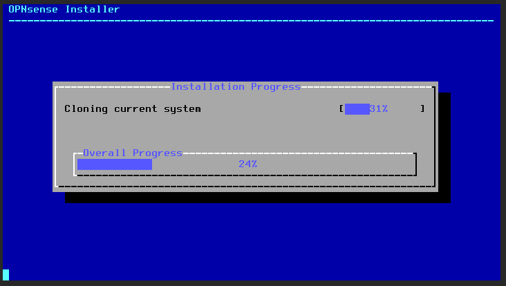
Once it’s done installing, it’ll give you the option to change the root password. You should change the root password then select “Complete Install”.
Initial Network Assignments
Once pfSense fully boots up, it’ll go through some configuration and then reach a point where it start a manual interface assignment process on the command line. The first question will be something like “Should VLANs be set up now?” Skip those VLAN assignment questions, you’ll deal with that later.
Next, pfSense will automatically detect the three Linux bridges you created and assign them names like “vtnet0” according to their MAC addresses. If you’ve forgotten which one is which, you can see the virtual bridges as they are numbered in the node network section of the Proxmox web user interface (WUI). That’ll allow you to identify the vmbrXX number assigned to the interface. With that, you can cross-reference how they correspond to hexadecimal addresses in the hardware tab for the pfSense VM. With the hexidicimal go back to the pfSense command line and identify them according to the naming scheme pfSense offers.
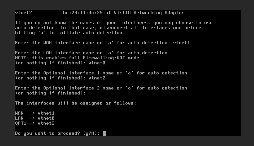
Use the hexidecimal address to assign the vtnetXX to the correct interfaces for wan, lan, and optional for the vlan.
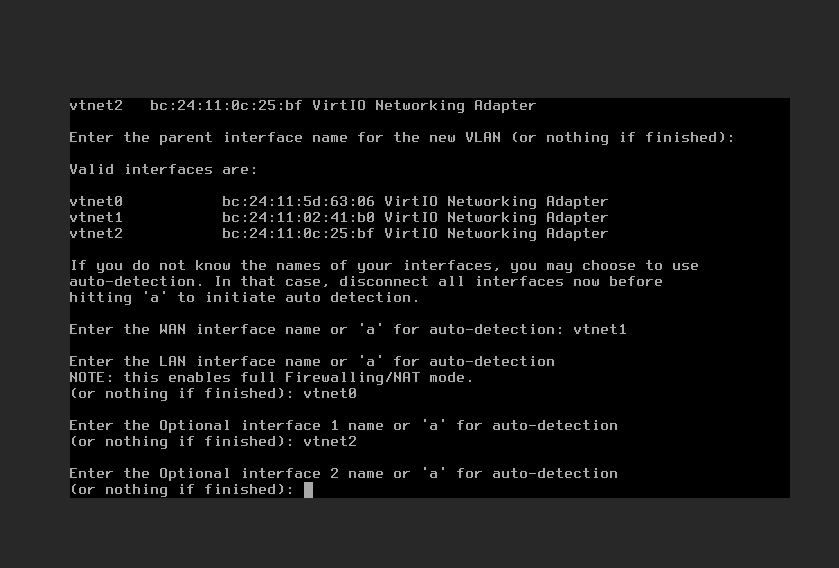 When you’re through, it’ll look something like this:
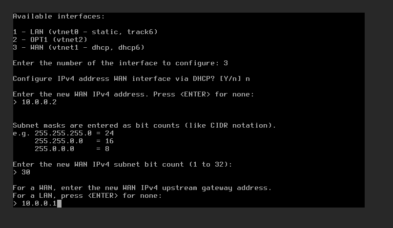
Next you’ll go through the IPv4 range assignments for WAN and LAN. Select option 2 to do so.
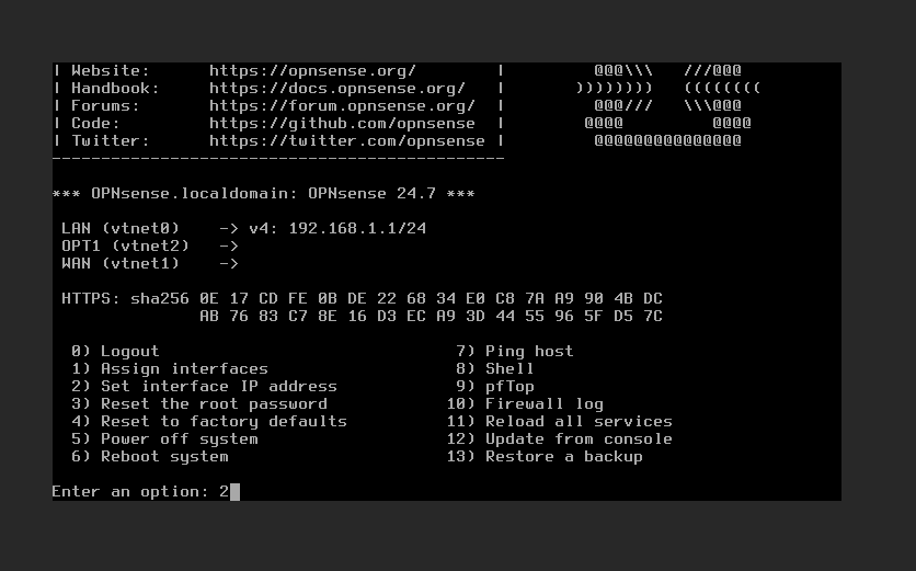
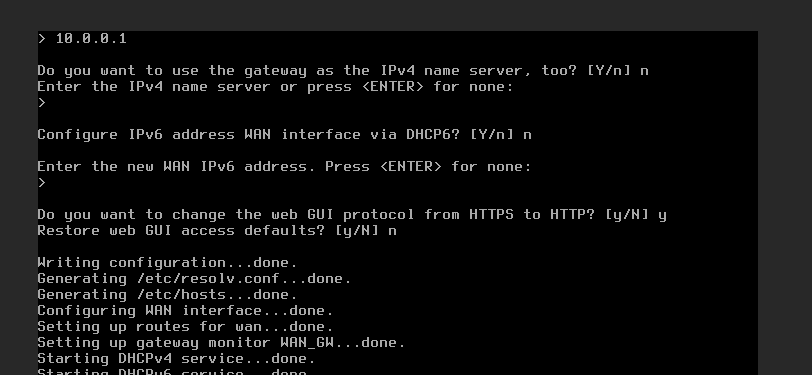
The WAN doesn’t need DHCP in the first question; for the second, the interface address is 10.0.0.2; for the third, the CIDR is 30; for the fourth, for the gateway is 10.0.0.1; and finally say no to the IPv6 questions. I chose HTTP instead of HTTPS, and was fine using the default for the WUI.
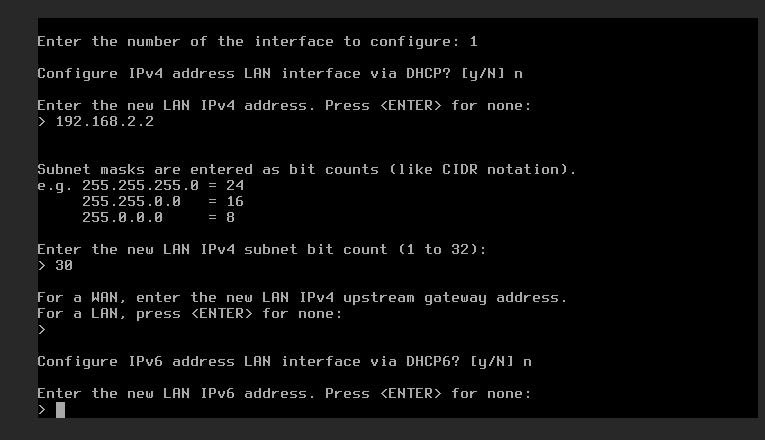
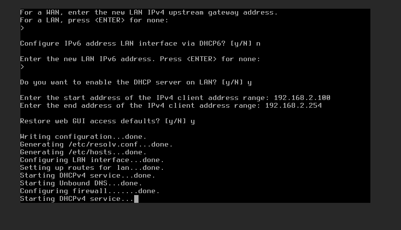
For the LAN you say no DHCP; set the interface address to 192.168.2.2; select the CIDR of 24 for the range; skip the gateway; and no IPv6 options. Default for the WUI was okay.
 Now you are done with the initial network setup. With some SSH tunneling we’ll proceed to the WUI as laid out in the next section.
Accessing the pfSense WUI
To sign in to the WUI for the firewall setup you’ll create a ssh local port forward as though you were using a compromised 1st target to pivot to a webserver offered on a 2nd. You’ll be connecting a random port on your attacking machine (8082 in the following example), the 2nd target IP and address (in our case the pfSense VM on port 80), and then the Proxmox IP and root user as the 1st pivot target.
Use the following ssh local port forward syntax on your local machine:
ssh -L 8082:<pfSense_IP_ADDRESS>:80 root@<proxmox_IP_address>
Now you can access the WUI at on your local machine at http://127.0.0.1:8082. If you have trouble, you might try https.
Using the pfSense Wizard
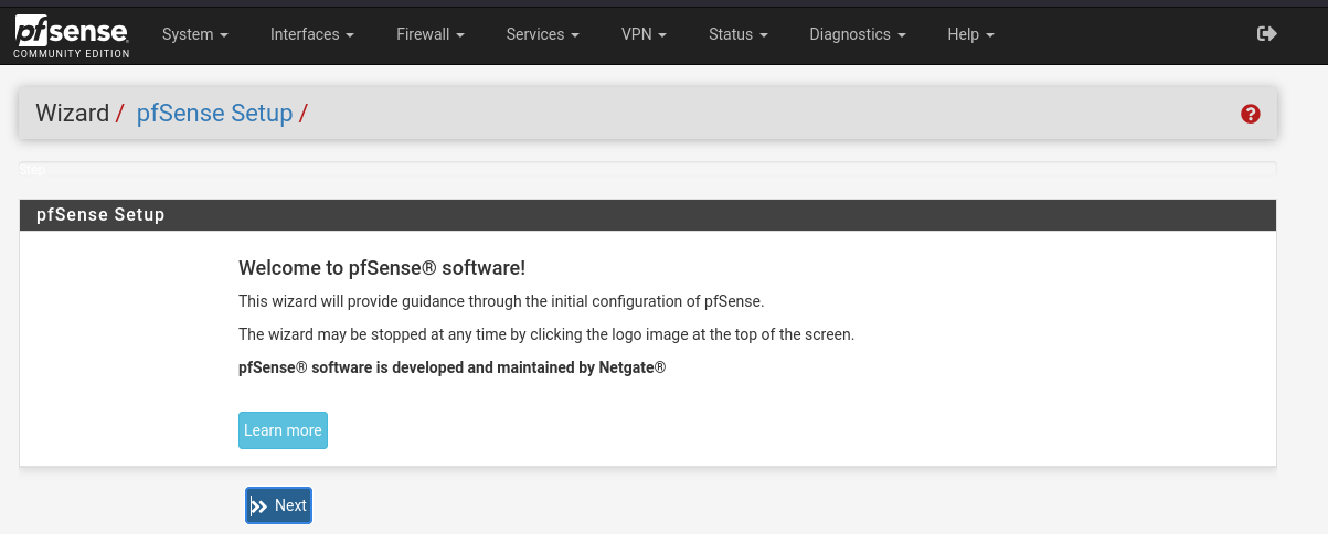
Once you sign into the WUI you should be greeted with a wizard. If not, look under the System dropdown for “Setup Wizard.”
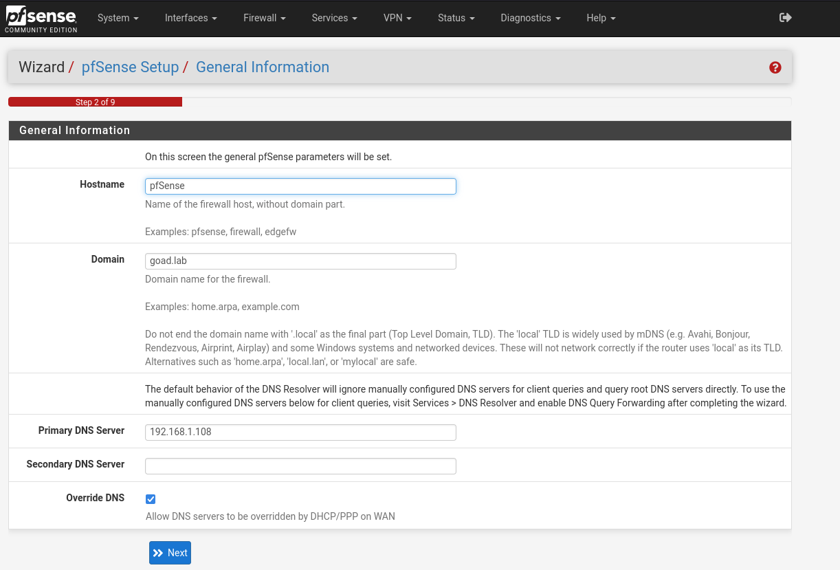
Select a domain name, and make sure the box for “Allow DNS servers to be overridden by DHCP…” is ticked. Additionally, for my network setup I had to specify my DNS server that is seperate from my router. That setup is a tad unusual, it may not apply to all use cases.
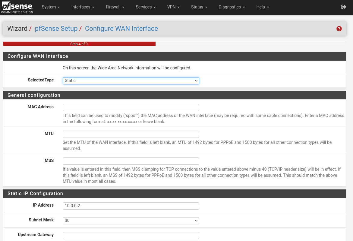
On the next page accept the default NTP servers and select your time zone. Then on the WAN interface keep static IP 10.0.0.2/30 with gateway 10.0.0.1.
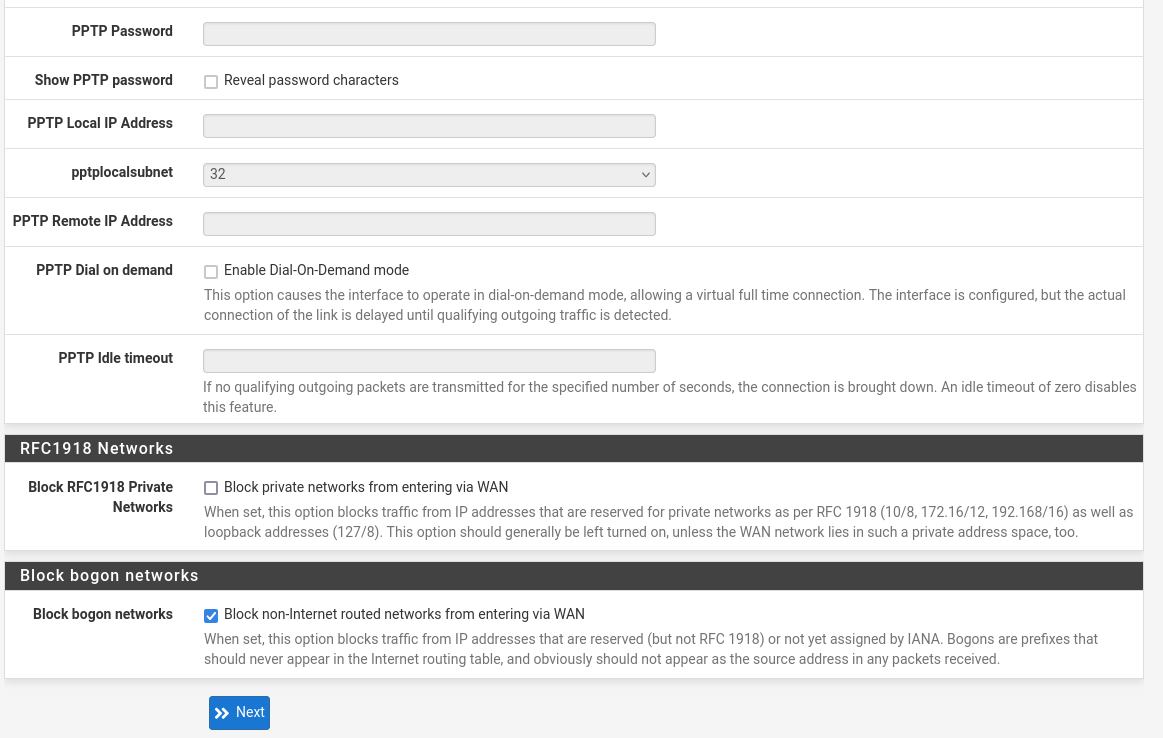
And uncheck the block RFC1918 private network.
Keep the LAN as you set it in the previous step above.
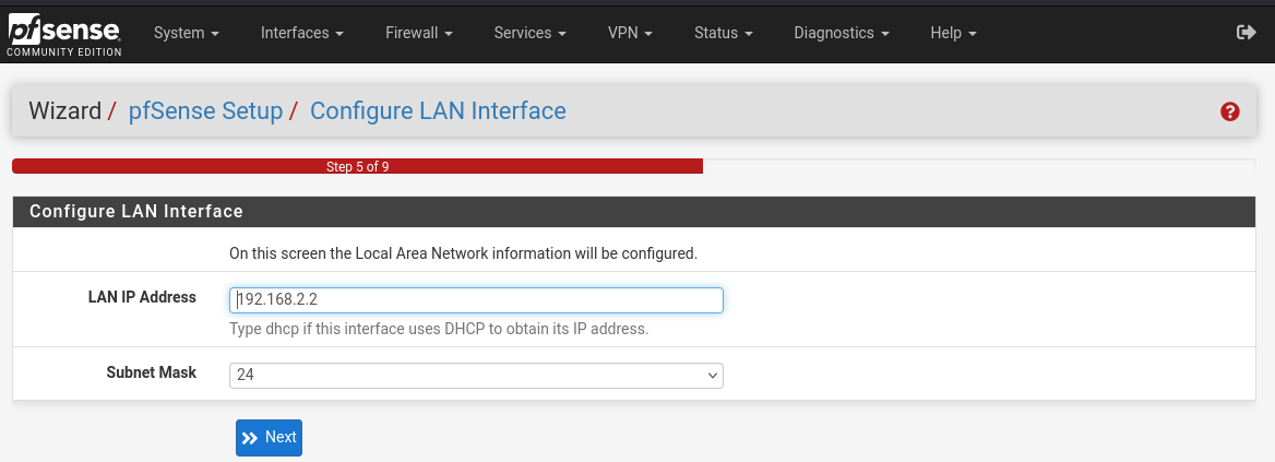 Change the password for root if you haven’t already. Finally, click reload.
Go to the System dropdown -> Advanced -> Networking tab -> Under the section Network interfaces check the “Disable hardware checksum offloading” box.
Click reboot (or go to Power > Reboot).
Networking and Firewall Rules
WAN
As Mayfly277 points out, our goal in this section is to redirect ip incoming traffic to the pfsense WAN network.
First we want to maintain our access. We will add an allow rule to the pfSense http interface granting access to the Proxmox host’s WAN address.
Configure the WAN firewall interface: Firewall > Rules > WAN to allow an ssh tunnel to pfsense http port.
Next, we’ll add a block rule.
While I don’t have a screenshot of what the firewall rule for the WAN interface looks like at this point, I do have the following photo from a later point in the configuration (it only adds another exception for the provisioning ssh tunnel).
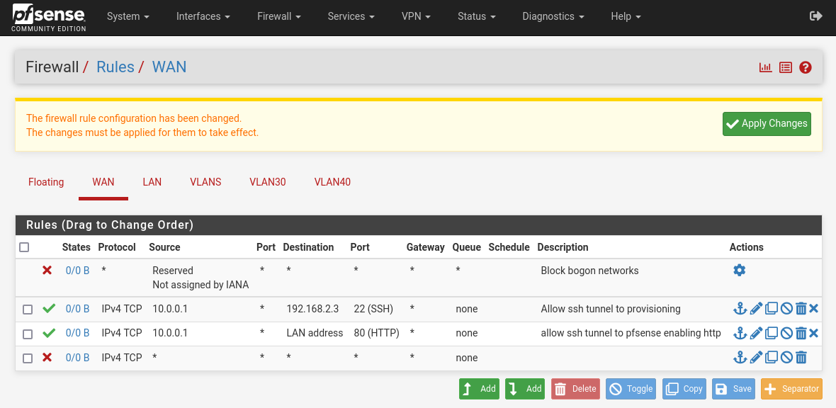
Next we’ll switch to the Proxmox command line and follow Mayfly277’s NAT adaptations (see his post for explinations):
echo 1 | sudo tee /proc/sys/net/ipv4/ip_forward
iptables -t nat -A PREROUTING -i vmbr0 -p icmp -j ACCEPT
iptables -t nat -A PREROUTING -i vmbr0 -p tcp --dport 22 -j ACCEPT
iptables -t nat -A PREROUTING -i vmbr0 -p tcp --dport 8006 -j ACCEPT
iptables -t nat -A PREROUTING -i vmbr0 -j DNAT --to 10.0.0.2 `
For the final step, we’ll make a modification by using the LAN IP of Proxmox instead of the public IP to translate outbound traffic from the WAN to our local network:
iptables -t nat -A POSTROUTING -o vmbr0 -j SNAT -s 10.0.0.0/30 --to-source <PROXMOX_LAN_IP>
Run ip r and route to verify that the entries look similar to Mayfly277’s.
iptables-save | sudo tee /etc/network/save-iptables
Then use a text editor like vi to edit /etc/network/interfaces, adding the following to the end:
post-up iptables-restore < /etc/network/save-iptables
VLANs
Now we create the VLAN interfaces by heading to the Interfaces dropdown -> VLANs and clicking the add buttom on the bottom right.
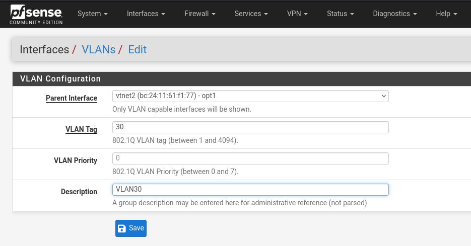 Select VLAN bridge (opt1) as the parent interface, and put in the first tag of 30 with a description.
Do the same again, but with a VLAN tag of 40 or whatever number you’re using.
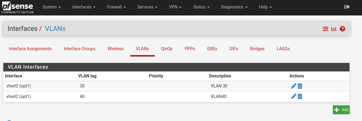
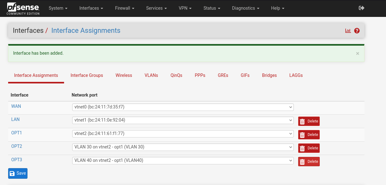
Then select the Interfaces dropdown -> Assignments and use the add button on the bottom right twice to add each of the VLANs you just created to the interfaces. You may have to hit apply settings. When you’re finished, it should look like this:
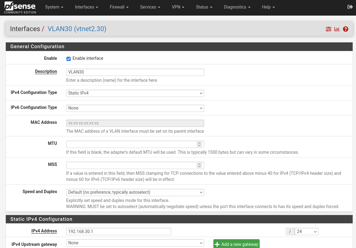
Then click on OPT2 on the right side and ensure the interface enabled box is checked at the top and that the IPv4 configuration type is set to static. Do the same for OPT3. You may have to apply changes after you save each time.
DHCPs
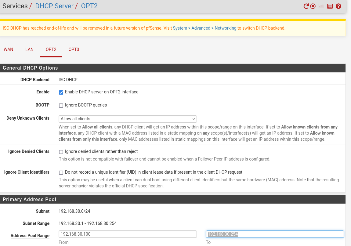
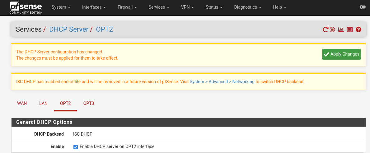
Now we’ll enable the DHCP servers on the VLANs. Go to Services > DHCP Server and click on one of the VLAN tabs (in this photo I hadn’t yet named them so they appear as OPT2 and OPT3). Ensure the “enable DHCP server on VLANXX interface” box is checked for the first, and enter in the range 192.168.xx.100-192.168.xx.254 replacing xx with your tag number. Same for the second VLAN but with the different tag number. Apply changes after each.
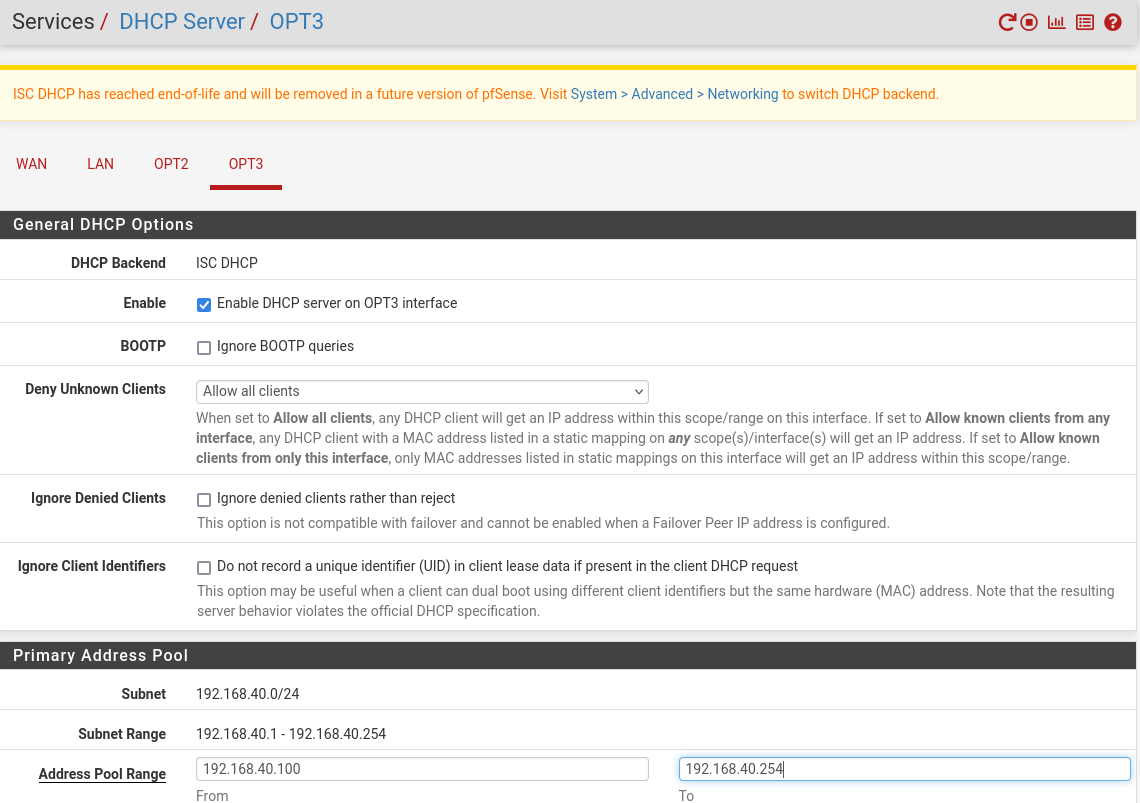
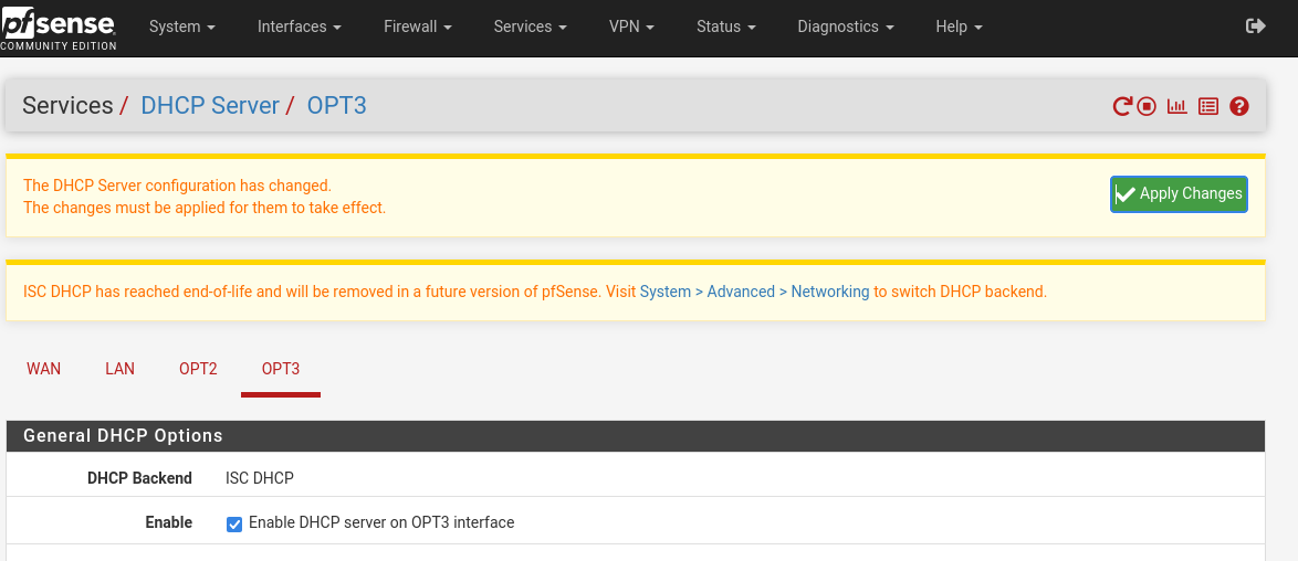
VLAN Firewalls
Now we’ll create an alias before setting up the VLAN firewall rules.
Head to Firewall -> Aliases -> green add button on bottom right. Give it a name, INTERNAL, and add the networks and VPN as seen below but changing for your GOAD LAN network:
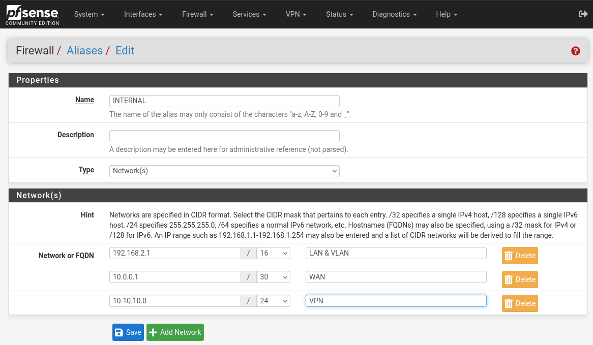
Apply changes.
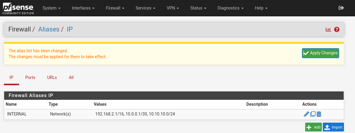
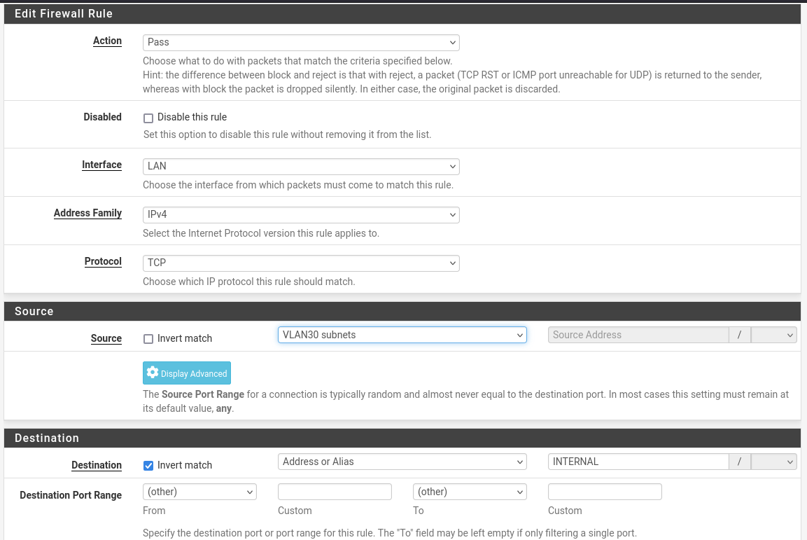
Now set up the firewall using the alias by heading to Firewall -> Rules -> LAN and adding a rule. You’ll enter the first of VLAN subnets as the source and invert match for the destination of an alias to the INTERNAL alias.
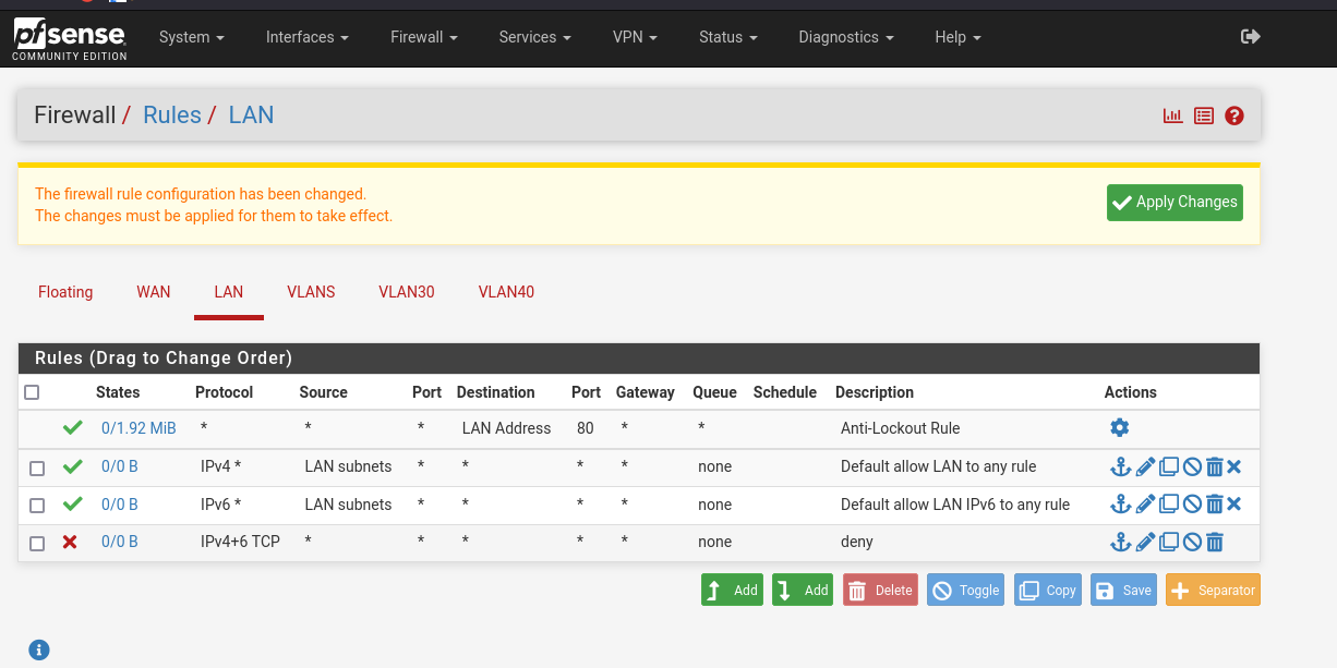
Then your LAN rules should look like this:
 I’m going to deviate from Mayfly277’s guide and end this post at this point for the sake of clarity.
Initial Networking Complete
That wraps up the initial portion of the networking configuration. Next we’ll work on creating the provisioning machine and its unique networking needs.
Resources
- Mayfly277’s blog
- Ben Heater’s blog
- Orange-Cyberdefense’s GitHub Repo
- Orange-Cyberdefense’s Proxmox instructions